How Does the CDI Work? As part of my series explaining how the various electrical black boxes work on the P200, I thought I would have a look at the inner workings of the Capacitive Discharge Igntion ("CDI") system fitted to most every bike. The animation below shows how the system works in motion, but it probably isn't glaringly obvious to most what is happening. Using the animation as a reference, I will describe the behaviour of the ignition system. This tutorial assumes a little electrical knowledge on behalf of the reader. Okay so if you're stuck on how it works, let's look at the parts of the ignition system in order. We'll start with the stator. 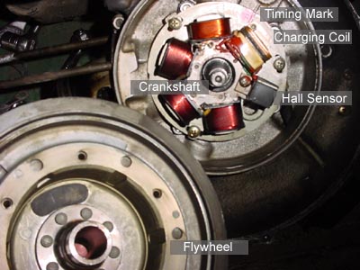
The flywheel is a large permanent magnet that spins on the crankshaft. It is magnetized at the factory and has a defined north and south pole. Think of it as a horseshoe magnet rolled into a circle. As the flywheel turns past the charge coil, the charge coil produces an alternating current from +6V to -6V. The CDI box has a collection of semiconductors that regulate the flow of electricity. The Rectifier connected to G1 on the box allows only the positive pulse enter the condensor, C1. So when the wave enters the CDI, the Rectifier allows only the postive part of the wave through to the capacitor and blocks the negative part. The trigger circuit is a switch, presumably using a transistor, thyristor or SCR. These components are basically gates that are triggered by the pulse from the Hall Sensor on the stator. They do not allow current to pass through to the other side of the circuit until they are triggered. Once a charge is induced into C1, it has no where to go, so it stays full for a few seconds until it leaks off. Once C1 is fully charged, the circuit can be triggered. This is why there is timing involved with the motor. If the condensor and stator coil were perfect, they would charge instantaneously and you could trigger them as fast as you wished. however, they require a fraction of a second to come to full charge. If the circuit triggers too fast, the spark from the spark plug will be extremely weak. Indeed, with higher revving motors, you risk the chance of triggering faster than the condensor can fill, which will affect performance (with misfires). The trigger pulse from the hall sensor feeds into the gate's latch and allows all the stored charge to rush through the primary side of the high voltage transformer. The transformer shares a common ground between the primary and secondary windings. In this configuration, we have an "auto-step up" transformer. Therefore, if you multiply the windings on the secondary side, you will multiply the voltage. Since a spark plug needs a good 30,000 volts to spark, there must be many thousands of wraps of wire around the high voltage or secondary side. When the gate opens and dumps all the current into the primary side, it saturates the low voltage side of the transformer and sets up a short but immense magnetic field. As the field collapses, the large current in the primary windings forces the secondary windings to hold the charge by producing an extremely high voltage. However, the voltage is now so high that it can arc through air, so rather than being absorbed or retained by the transformer, the charge travels up the plug wire and jumps the plug gap. When you go to kill the motor, you use a switch on the headset: either the key or the kill switch. The switches ground out the charging circuit so the entire charging pulse is sent to ground. Since the CDI can no longer charge, it will cease to provide spark and the engine will slow to a stop. 
All Material Copyright 2001-2026 by Richard Hoar. Use at your own risk. |