How Does the Voltage Regulator Work?
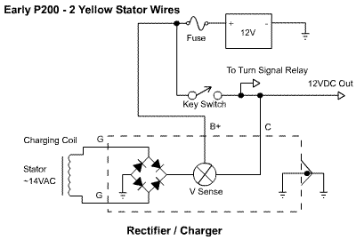
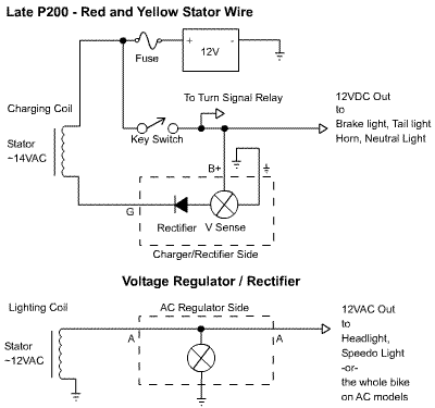
The Voltage Regulator / Rectifier on the P200 is a black box that performs two distinct funtions withing the same box. The first function is battery charging. The battery on a Vespa requires constant charging in order to run many of the indicators and safety features of the bike (and starter motors is your bike is so equipped). The second function of the regulator is to regulate the AC power for the headlight and spedometer light. The regulator/charger box is probably the most advanced collection of circuits on the bike, but it is the least prone to failure.


These circuits contain the layout of the battery charger / rectifier circuit. A battery is a pretty finnicky device as far as power input is concerned. The Voltage regulator has to satisfy two goals: 1. provide a DC input source and 2. Provide a voltage of roughly 14 Volts. The regulator employs a rectifier in order to change the power from AC to DC, but it is not used as we are used to seeing it in North America. It attaches on the ground side of the battery as is common in conventional current circuit layouts. Next to the rectifier is the Voltage Sense Deivce, which I can only assume it is driven by a handful of semiconductors. The sensor accomplishes two tasks, it limits the upper charging voltage to 14.4V and charges the battery with more or less current depending on the battery's condition. The battery's positive terminal feeds back into the circuit to help the regulator decide how hard to drive the charger. Under normal conditions, the charger works very little, simply trickle charging the full battery. But as the battery gets weaker, the charger senses less voltage and boosts the charge current. When the battery dies, or the fuse blows, the voltage sensing assumes a completely dead battery and drives as hard as it can. This circuit is current limited so it will not just explode, but it would be a good idea to fix any problems with the battery circuit so that the battery doesn't go completely dead.
The bottom circuit (in the late P200 diagram) is a layout of the AC regulator. The soul purpose of this device is to limit the overvoltages from a high revving engine. As the engine spins faster, the overall voltage goes up past the operating voltage of the headlight. That kind of overvoltage can take out an expensive headlight, so as a safeguard, the power from the stator is routed into the voltage regulator. All power that surpasses a threshold of about 14 volts is shorted to ground. It doesn't matter which way you wire up the circuit for the two "A" inputs, since the circuit is not polarized. This circuit is not current limited, so running with no load (ie dead headlight) will make the regulator overheat. If your headlight goes out and there is no immediate replacement, disconnect the wire from the "A" wire that goes to the stator.


All Material Copyright 2001-2026 by Richard Hoar. Use at your own risk.
|